How to Purchase a Regenerative Thermal Oxidizer (RTO)
Helpful guidelines for specifying & purchasing an RTO
Selecting & Purchasing an RTO does not require an in-depth knowledge of regenerative thermal oxidizer operation or features – at least not right away. What is critical, initially, is an understanding of details you already know well: your manufacturing process and your business goals. Documenting these into an RTO specification will be a springboard for success. Table 1 will provide a useful guide for assembling an RTO specification.
Specifying and selecting a Regenerative Thermal Oxidizer (RTO) for control of your industrial air emissions can be a daunting task. Fortunately, there are tools available to increase your potential for success right from the start.
It does not require an in-depth knowledge of regenerative thermal oxidizer operation or features – at least not right away. What is critical, initially, is an understanding of details you already know well: your manufacturing process and your business goals. Documenting these into an RTO specification will be a springboard for success. Table 1 will provide a useful guide for assembling an RTO specification.
Benefits of Developing an RTO Specification:
Documenting your process conditions and your business goals in an RTO specification will help ensure potential oxidizer suppliers will bid to the same baseline. Having easily comparable bids will simplify your proposal review process. It also will also help ensure:
The RTO will be sized for the specific range of conditions expected now and in the future
Only necessary oxidizer features will be quoted by suppliers
Any RTO operating cost comparisons will be based on your specific operating conditions
A clear project scope – oxidizer location, mechanical installation, wiring, piping, ductwork, and dampers desired
Air permit writing is not addressed in this article, but it's recommended to have early involvement by your in-house environmental engineer or an outside consultant. Their knowledge of regulations specific to your locale, facility and process will be valuable for the development of an emission compliance plan and for specifying the RTO performance required.
TABLE 1. Checklist for Specifying a Regenerative Thermal Oxidizer (RTO)
Information Needed
Why Needed
Case Study: Source 1
Process Description
Emission Source Description
Laminator
Airflow (scfm) scfm = standard cubic feet per minute
RTO (typically) sized based on the airflow capacity of all emission sources combined. Note: a high VOC concentration (>15% LFL) or a high humidity airstream may increase the required RTO capacity.
8,500 scfm
Air temperature (F)
Determines the fan sizing and insulation needs on the RTO. Note: actual exhaust temperature; not oven operating temperature.
225 F
VOC Concentration: Normal (lb/hr)
Determines optimal thermal efficiency (TE), and special features needed such as hot bypass. Would lower TE be better for high VOC? Would higher TE have good ROI for low VOC streams?
50 lb/hr
VOC Concentration: Peak (lb/hr)
Can determine RTO size and optimal thermal efficiency. Peak values could cause nuisance over-temperature faults if not consider in design.
60 lb/hr
VOC Mix
Determines special design considerations. Condensable VOCs may require bake out, other VOCs extended dwell time for proper destruction; high odor VOCs may require odor control features; corrosive VOCs (halogens) special metals of construction.
40% MEK 60% Toluene
Particulate (grain/hr; size, make up)
Determines special features or filtering needed to protect susceptible ceramic media beds. Features such as bake-out or media wash downs. Filters such as fabric banks or electrostatic precipitators.
None
Moisture Content (%, RH)
High moisture airstreams may require increased RTO capacity to accommodate the gasification of the water at operating temperatures.
Ambient <50% RH
VOC Destruction Efficiency (DRE) (%)
Determines RTO design and features. Permits will specify an overall control DRE which is determined by capture efficiency (% of VOC captured by hoods or ovens) and RTO DRE. Capture efficiency can be proven by testing, or possibly applying an agreed upon standard for your industry. Consultants are helpful here.
98% RTO 80% overall
Current Operating Schedule
Sets baseline for supplier’s operating cost estimates.
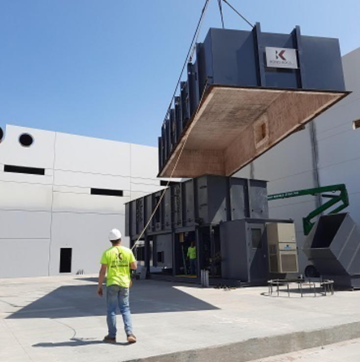
Consider truck and crane access, future building expansion, and ductwork length (a major cost factor).
Outdoors, wall adjacent to process oven. Ductwork thru roof dropping down wall to RTO.
Future Growth
Equipment costs are a large percentage of the project cost (50-60%). May be wise to plan for expansion expected in 2 years; not 4. The incremental cost for more capacity in this first RTO is nominal and allows you to avoid all the other costs associated with sourcing a second RTO (shipping, concrete pad, installation, commissioning, permitting, project management).
Additional Process identical to source 1 in late 2023; another in 2025.
Visible Plume (Yes/No)
An RTO has a puff of VOCs released to the exhaust stack every 2-4 minutes. Puff captures can eliminate the visible plume if needed.
No
Process Sensitivity to Pressure Pulse (Yes/No)
An RTO switches flow direction every 2-4 minutes creating small pressure pulses back to the process/oven. Sensitive processes can have their product tip over or cause coating thickness variations. Rotary valves have much lower pulses than poppets.
No
Heat Recovery Desired (Yes/No)
RTO exhaust temperatures exceeding 300F may have good ROI for heat recovery.
Yes, loading dock heating
Analyzing Regenerative Thermal Oxidizer Proposals
Once proposals are received based on your RTO specification, the next step is evaluating the various proposed regenerative thermal oxidizers for suitability and long-term performance. What should be considered in the evaluation process? Table 2 will provide high level criteria for evaluating RTO systems and individual components.
RTO Components & Guidance
Review the proposed RTO components and overall system with the second checklist (Table 2) to differentiate one RTO system from another. This will help you evaluate each RTO from a position of knowledge and understanding, allowing you to ask informed questions of each supplier.
Main fan horsepower (HP) can vary significantly between suppliers. HP is determined by the airflow, temperature and pressure drop across the RTO. Pressure drop is greatly determined by the air speeds through the RTO and the ceramic media bed design. Here is where the buyer must be diligent to ask questions about the overall system itself. Horsepower and thermal efficiency in quality RTO systems are optimized. Lower quality designs squeeze more air through a smaller, lower cost unit but resulting in lower thermal efficiency.
What is the pressure drop of individual components (see Figure 1) and full system?
Switching valves
Poppet valves and rotary valves have decades of proven performance with ultra-low leakage rates. Some ovens have sensitivity to pressure pulses from poppet style valves. Rotary valves have lower pulses and some use electric drives, great for cold weather conditions.
Is my process sensitive to a pressure pulse?
Ceramic media beds
Very critical to analyze together with fan horsepower (above). Ceramic media bed design is not art, but science. Inform yourself with the projections provided by ceramic media suppliers on-line (see figure 2 for an example). These can be compared to the thermal efficiency (TE) in the RTO proposal. RTOs are by far the most efficient oxidizer option but must be optimized to achieve the best performance. Actual TE of a ceramic media bed design utilizing the same ceramic media type can vary significantly when run at different bed volume, bed depth and airspeeds. This is very important as decades of utility spending are impacted by the decision. As a rule of thumb structured ceramic media bed designs provide a higher thermal efficiency and lower fan horsepower in a smaller footprint than random packed ceramic media, but at a higher capital cost.
What is: Face area, bed depth, and airspeed through the ceramic media bed? Media type used in the bed? Performance curves available? Is a higher TE bed design available?
Burner and Fuel Injection
Some RTO systems use a nozzle-mix burner for heat up and normal operation. Fuel injection is offered on some RTOs to take over as the heat source during normal operation; offering as much as 20% fuel savings.
Supplier’s fuel injection experience?
PLC controls
Familiarity with the PLC model internally and by the RTO supplier should drive the PLC selection. Insist on remote access capability for maintenance/troubleshooting.
RTO Shell & Insulation
Cost savings will be evident in some designs in this area. An RTO has a (typically) mild steel shell that is internally insulated to protect the shell from 1600F+ internal temperatures. The large spans of shell surface area are stiffened (3-4” channel) for integrity and long life. Combustion chamber insulation depth is typically 8” at 8-10 PCF; and sometimes reduced (6”D) in the ceramic media bed. Radiant heat loss can be a significant long term utility cost.
Shell material / thickness? Stiffener spacing? Insulation thickness / density?
Cold Face Support
Cold face supports are critical but typically simple structural support of the ceramic media that allows air to pass through the “face” of the support through the ceramic media.
How long has this cold face design been utilized in RTO design? Maximum temperature allowed?
RTO Assembly
Significant advances in RTO design have occurred in this area reducing project costs by easing RTO assembly and simplifying shipping. Weld-together systems are rare.
Is welding required for assembly? Why?
Non-Technical / Subjective Considerations
-Proven RTO/supplier capability in this industrial heating application -After-sale support
References available?
The last item in Table 2 is critical: Is the RTO manufacturer and their RTO design proven in your particular industry and application? If this criteria is met, then a more in-depth analysis of the proposal should be made, beginning with the major components of the oxidizer system. These components must be assessed individually and as a system. Table 2 looks at the components that make up an RTO system, and it provides guidance on their importance and possible questions to ask.
One significantly important evaluation will be the ceramic media bed design. This can seem daunting but an in depth analysis of the offerings of each suppliers RTO will pay dividends for years to come in reliability, fuel efficiency, and longevity of the RTO. You will find the charts below very useful in your analysis. For assistance in interpreting the charts or the particular ceramic bed design you are evaluating, feel free to contact us and one of our experts can assist you.
Structured ceramic media bed designs may provide higher thermal efficiency and lower fan horsepower in a smaller footprint than random packed ceramic media – but at a higher capital cost. Credit: Lantec Products
Pressure Drop is greatly determined by the air speeds through the RTO, as well as the ceramic bed design. Credit: Lantec Products
The actual thermal efficiency of a media bed design utilizing the same ceramic media type can vary significantly when run at different bed volume, bed depth and air speeds. Credit: Lantec Products
Case Study
A case study can help illustrate the process of specifying RTOs and reviewing proposals. In table 1 (column 3) above is a case study with hypothetical process conditions and business growth plans that we will use to select a Regenerative Thermal Oxidizer.
The hypothetical application in this case study is simple, with no particulates or halogens in the airstream and light VOC concentrations. A standard rotary or poppet valve RTO without additional features will be the offering from most suppliers. Insulated valves and ductwork will be suggested due to 225°F (107°C) process temperature.
Based on these application details, the likely recommendation for the hypothetical application is a 17,000 scfm capacity RTO with insulated/clad poppet or rotary switching valve; structured or random ceramic media; fuel injection; mild steel construction; and insulated ducting/valve. The size recommended (17,000 scfm) addresses the two-year growth plan. Planning for four years out has too many unknowns to justify additional investment at this time.
Because a Regenerative Thermal Oxidizer with poppet valves will perform as well as a rotary valve RTO for Source 1, the switch valve selection can be based on value. The ceramic media bed designs must be evaluated individually. Secondary heat recovery has potential ROI because the RTO exhaust temperatures will be above 300°F (149°C).
Conclusion
Successfully navigating the selection of your regenerative thermal oxidizer (RTO) from specification through proposal review does not have to be overwhelming. These simple checklists will help you build a well-thought-out RTO specification and also guide a methodical review of RTO proposals. With these checklists, your team – and any needed outside environmental engineering support – can assemble a clear, forward-looking plan for your current and future emission control needs. This specification then provides a solid baseline that RTO suppliers can quote from – and will thank you for – and it will ease your proposal review process. These checklists and guidelines are not all you will need, but they do provide high level maps to guide your efforts.