Regenerative Thermal Oxidizer Types
Available RTO Options and Configurations
RTO systems offer great flexibility to manufacturers striving for sustainability in treating their industrial air emissions. Most manufacturing airstreams requiring emission abatement fall within the operating range of an RTO, which allows this super-efficient oxidizer technology to be used for many applications.
Regenerative thermal oxidizers are considered the go-to solution for reducing VOC emissions from processes that have high airflow volume but low VOC concentrations. But now, with cost-saving design improvements, RTOs have supplanted most other oxidizer technologies (catalytic/thermal) for even smaller airflow volumes. In addition, high VOC concentration airstreams can be treated with an RTO through various add-on features. These features control the high exothermic heat release present in these airstreams. And with some of these high concentration applications, the high heat release can be captured for secondary purposes (heated air/water, steam).
RTOs can also be successfully implemented in applications with visible emissions or odor control concerns with the addition of extra ceramic media beds, or a puff capture. Through wise innovations over 3+ decades RTOs have become a staple oxidizer technology for most industrial airstreams. The information below will help you understand both the common and special configurations available to accommodate such a wide variety of applications in industry.
RTO Chamber Configurations
During operation of a regenerative thermal oxidizer, flow direction changes achieved by a switching valve may trap and subsequently exhaust untreated air. This is typically called a “puff” because it will appear as a visible puff in the RTO exhaust if the VOCs being treated are visible to the eye.
While an RTO system still achieves 98+% VOC destruction- even with this puff- the fact that the puff is visible in some applications manufacturers may desire to “capture” the puff. This may be best treated with the addition of a third chamber or a puff capture feature.
Two-chambered RTO
The most common type of RTO, a two chambered RTO alternates air flow direction between two ceramic media beds/chambers containing heat exchange media. During the split-second flow reversal period, a portion of dirty, untreated air will be flushed out of the RTO into the atmosphere (described as a “puff” above). Even though a two-chamber RTO produces very high VOC destruction (98%+), the visible emissions, or the odor contained in the small amount of emissions in the “puff” may be a nuisance to neighbors.
Three-chambered RTO
The third (or any additional number) chamber in these systems traps any dirty, untreated air that is generated during the air flow reversal period. This trapped “puff” is then treated by routing the puff back through the RTO along with the main incoming process emission airflow. This allows the VOCs in the captured “puff” to be destroyed (oxidized), before exhausting the cleaned air into the atmosphere. Three (or 5, 7, etc. ) chamber systems are common. The additional chamber provides a way to eliminate visible emissions, and also greatly reduce or eliminate odor in the RTO exhaust.
Two-chambered RTO with Puff capture
To treat the “puff” (or to increase VOC destruction performance) of a two chamber RTO, a “puff capture” feature can be added to the two chamber RTO. This feature captures the dirty, untreated air that is generated during an airflow reversal period. The captured puff is then bled back into the RTO inlet for treatment. This puff chamber has a much lower capital cost than adding a third chamber, and a much smaller RTO footprint- while accomplishing the same purpose of capturing the “puff”.
Not sure which type of RTO you need?
Contact us or fill out the quote request below. Our experienced technicians will walk you through the RTO options available and will recommend the best configuration for your needs.
Flameless or Electric Regenerative Thermal Oxidizers (RTO)
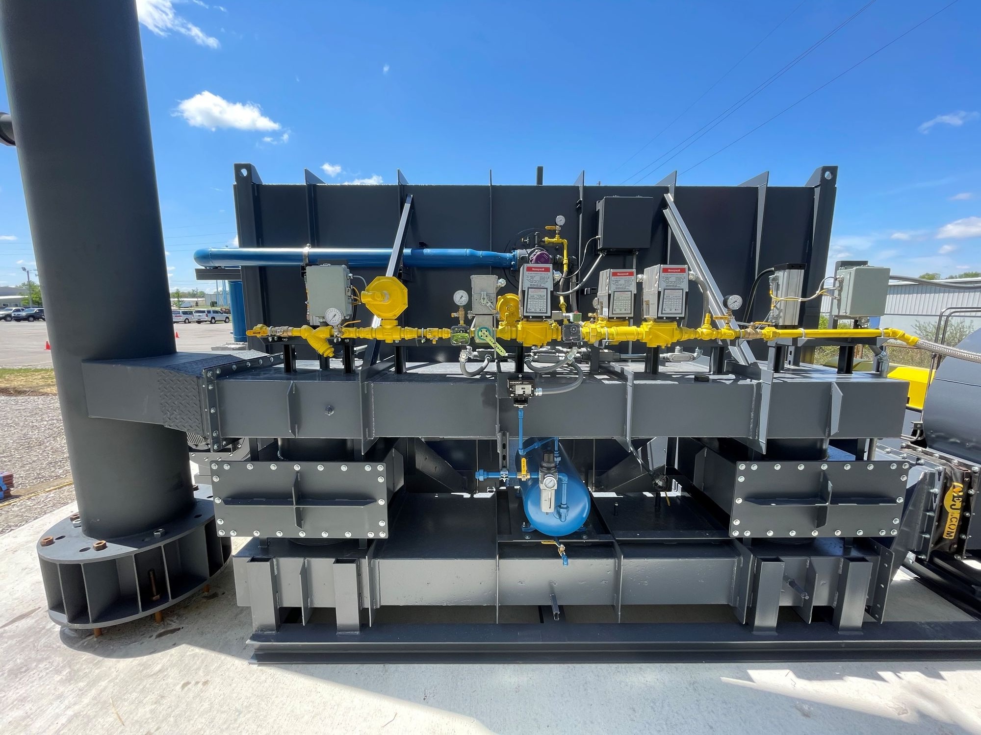
Flameless* RTOs incorporate natural gas injection as the supplemental heat source in the RTO during normal operation. Since a burner is not the heat source, the RTO operates without a flame, or "flameless". Fuel injection is possible in an RTO because an RTO operates with temperatures above the auto-ignition temperature of natural gas. The primary advantage of flameless RTO systems is fuel savings, with an additional advantage of low NOx emissions. The fuel savings results from operating without the supplemental combustion air that is required when operating with a natural gas burner. NOx emissions that would originate in a natural gas burner, due to incomplete combustion of the fuel/combustion air mixture, are avoided by utilizing natural gas injection.
Flameless RTO: Electric Regenerative Thermal Oxidizer
Some RTO technologies, commonly called electric regenerative thermal oxidizers, utilize electric heaters for initial heat-up of the RTO to approximately 1800F. Once heat-up is accomplished, the fuel injection feature is initiated and provides the supplemental heat needed for normal operation, allowing the electric heaters to be shut off. These systems consist of a single heat-transfer (ceramic media) bed containing electric heating coils embedded in the ceramic media. The drawback of electric heating coils is that the electric coils suffer failure quite often due to the intense heat the element is exposed to. While the RTO can continue running with fuel injection, once unit is shut down it cannot be re-lit with failed electric heaters, causing extended downtime (days to weeks) and therefore production losses.
Flameless RTO: Conventional Burner Heat-up
Some RTO’s are designated as “flameless RTOs” yet still utilize a burner for initial heat-up of the RTO. Like the electric heated units, the burner (with a flame) heats up the RTO to operating temperature, but then switches over to fuel injection to maintain the RTO temperature during normal operation, allowing the burner to be shut off.
*Discussion of terminology- Flameless RTO: An RTO needs an initial heat source to bring the RTO up to operating temperature before natural gas injection can be safely initiated. This initial heat up is accomplished with a burner or electric heating coils. So, contrary to the designation “flameless”, RTOs with a conventional burner still require a flame to accomplish the initial heat-up of the RTO. An RTO with a natural gas burner used for initial heat-up of the RTO will sometimes be promoted as "flameless". It is not truly flameless during heat -up , but after heat-up with the burner, it operates without a flame. The terminology is a bit confusing. The term “flameless RTO” truly only applies to electric heated RTOs.
RTO Air Flow Valve Types
All regenerative thermal oxidizers (RTOs) operate on the principle of airflow reversal. Flow reversal is necessary to achieve the regenerative heat exchange performance which provides an RTO’s exceptional thermal efficiency. All flow direction changes require a mechanism to reverse the airflow direction. Some RTOs incorporate poppet valves, others use a rotary valve that is either indexed or continuously rotates.
Poppet Valves
These systems actuate opposing poppet valves to achieve flow direction changes. Typically these valves are air cylinder-driven with metal-to-metal sealing surfaces. The valves actuate simultaneously every 2-3 minutes. Poppet valve systems are the most common valve, and are normally the lowest capital cost valve option. They are exceptionally reliable as long as there is proper compressed air moisture control. The flow direction changes in a poppet valve system can introduce pressure pulses back to the process. These are small pressure pulses in properly designed RTO systems, and only an issue for sensitive manufacturing processes.
Indexing Rotary Valve
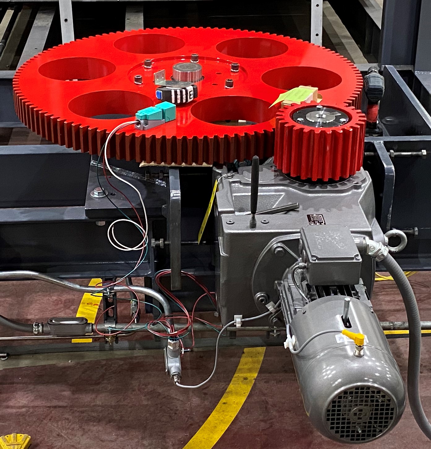
These systems index a rotary valve to direct airflow into the multiple chambers on the RTO (2 chambers to 12 chambers). The valve indexes every 2-3 minutes for two bed systems, and every 15 seconds for 12 chamber designs. The valve is driven via a pneumatic rack & pinion drive, or an electric gear motor & variable speed drive. The electric drive is the most common today because of its reliability and low maintenance.
Continuous Rotary Valve
This valve design continually rotates the valve with an electric gear motor and variable speed drive. As the valve slowly rotates it re-directs airflow into and out of multiple beds. These continuous rotary valves are sometimes called “valveless” RTOs.
Contact the RTO specialists at Kono Kogs to help you decide which regenerative thermal oxidizer is right for your needs.
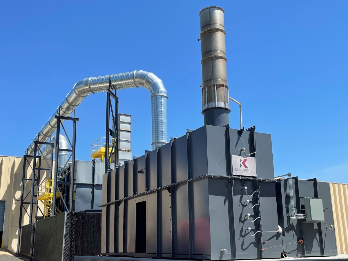
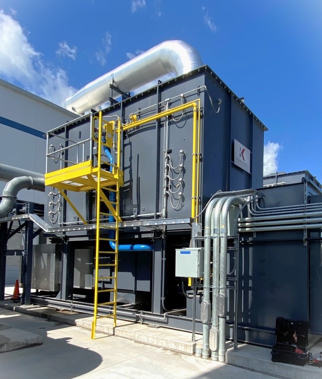
RTO Installation & Ductwork Treating Flexographic Printing Emissions
Kono Kogs refurbished & installed a second refurbished regenerative thermal oxidizer (RTO) for this major flexographic printer